

If you haven’t seen my previous Arduino + Bluetooth + RGB LED tutorials, please check them out from here, before you start this one.
– Tutorial 1 Make the Arduino + Bluetooth + RGB LED
– Tutorial 2 Make this App (older version)
– Tutorial 3 Make a nigh lamp
In this tutorial, I will add RGB slider bar under the bottom of the App using App Inventor 2 (AI2) from MIT to allow users to adjust the particular LED brightness. This feature was requested by quite few of visitors. Hope you will enjoy this one!
For whatever reasons you do not want to do this yourself, please download this App from Google Play Store directly. It’s FREE!
Screenshot of RGB LED Controller:

Here is screenshot of the component layout in App Inventor 2 for your reference.


Screen1.Initialize block is to reset App components status and set ColorPicked at x1, y1. The ColorPicked variable is used to store x1, y1 coordinates which are exact positions where users finger tip location on the display.

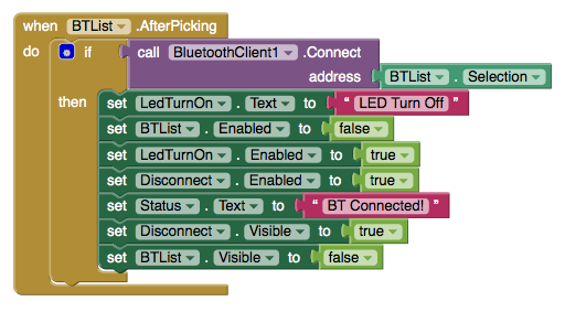
This part is considered as Bluetooth initialization to get nearby Bluetooth client list into the App.


The following three big blocks process the R, G, B sliders respectively.
Each time a slider’s position changed, the App reflects the R/G/B value changed and save the value into Color_Code_to_BT variable and sends the new color code through SendBTCommend2 block to achange RGB LED color.

This block works the same as the one above except it only handle Green color value.

This block works the same as the one above except it only handle Blue color value.


The block blow is used to update RGB color to Arduion when user’s finger touch on any part of the screen or in this case we only focus on the color wheel.


– Tutorial 1 製作 Arduino + Bluetooth + RGB LED
– Tutorial 2 自制 APP (本篇為新版APP,加入了 R.G.B 顏色拉桿)
– Tutorial 3 製作夜燈
如果你不想自己動手做這個 APP, 請你到 Google Play Store 免費直接下載!
在本篇教學裡,我們將修改前一版的 V2.0 APP,使用 App Inventor 2 (AI2) 加入 R.G.B 三個顏色拉桿,讓使用者可以自行調整每個顏色的強度,進一步改變 LED 的顏色。會加入這個功能的主要原因是很多讀者都留言要求這個功能!讓我們開始動手吧!
V3.0 APP 的畫面如下:

這是 AI2 App 元件的畫面參考圖,你也可以依自己的需求作調整位置/大小等等⋯⋯
首先先在AI2中設定幾個變數如下:
下面的區塊是 AI2 的螢幕啟動設定,除了設定一些參數之外,也把 ColorPicked 設在 x1, y1 的位置。 ColorPicked 這個變數是用來儲存螢幕上,使用者正用手指點下的 x, y 位標。
BTList.BeforePicking 是設定 Android 手機上所偵測到的藍芽裝置清單。
以下三個區塊 R.PositionChanged, R.PositionChanged 和 R.PositionChanged 主要是用來處理本次新增的 R, G, B 顏色拉桿。例如 R 拉桿位置改變時,這個區塊就會把 新的 R 顏色值和原來的 G, B 顏色值整合存入到 Color_Code_to_BT 變數,透過 SendBTCommend2 區塊送到 Arduino。
這個區塊負責 R.PositionChanged 其運作方式和上面一樣。
這個區塊負責 G.PositionChanged 其運作方式和上面一樣。
這個區塊負責 B.PositionChanged 其運作方式和上面一樣。
Canvas1.TouchDown 區塊主要是處理手指點在調色盤的每一個位置的顏色,快速即時的把當時的顏色回報到 Arduino。
Canvas1.Dragged 區塊主要是處理手指滑過調色盤的每一個點,快速即時的把當時的顏色回報到 Arduino。
看完後是不是很想動手試試這個 APP?請由 Google Play Store下載 RGB LED Controller V3.0 with R/G/B Color slider APP。如果你已經下載之前的版本,你應該可以以直接在手機上做更新。




V3.0 才有三色拉桿喔!
是要增加一個按鈕嗎?
只要在迴圈裡加入亮/暗的指令,不會很難喔!
Here is the link to the RGB Color LED Controller
App: https://play.google.com/store/apps/details?id=appinventor.ai_yuanryan_chen.BT_LED&hl=zh-TW
Hi David,
Check this post for Arduino code.
http://stonez56.blogspot.tw/2014/09/arduino-android-led.html