

Android control color RGB LED using HC-05 Bluetooth with Arduino(Part II)
You probably have seen my first part of Arduino hardware setup tutorial. If you haven’t please visit here: My previous Arduino (Part I tutorial).
After few weeks of struggling with MIT App Inventor 2, I finally completed my second generation of Color LED Controller V2.0 App.
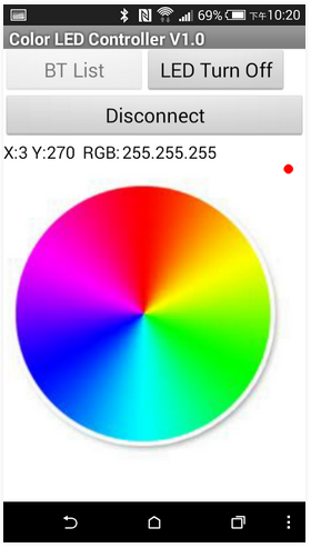
Basically, 2nd generation of Android APP shows a color RGB wheel on the display and you might pick any color on the display to wirelessly change the RGB color accordingly. With glide/drag capability built in the App, you may glide your finger through the color wheel to see RGB LED changes color gradually.
For the Arduino part, all the code stays the same. Yes, I haven’t modified a single line of code in the Arduino.
Please watch the video below to see how it works! 🙂
Here are the App coding screenshot for your reference:
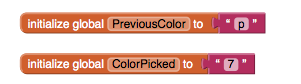
0) Sorry blog readers….here are the two missing global variable blocks…. 🙂
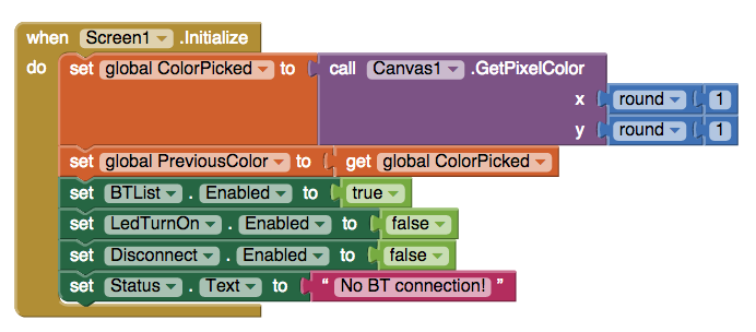
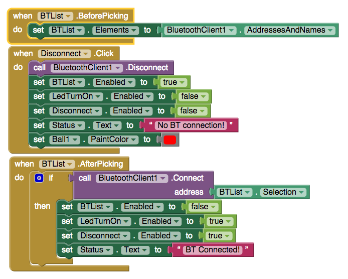
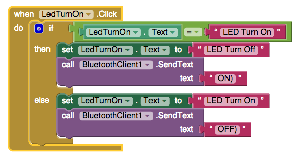
3) The button to turn on/off LED
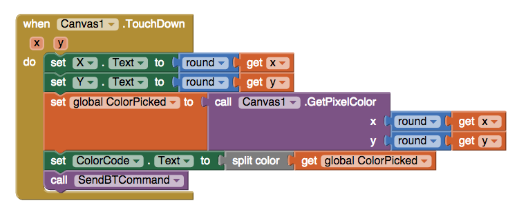
4) Code for touch on the color wheel to change LED color
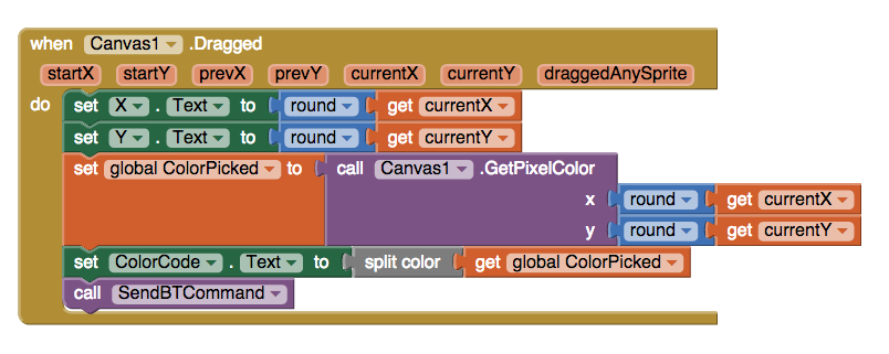
5) Code for Glide/Drag finger across the color wheel to see the color change accordingly
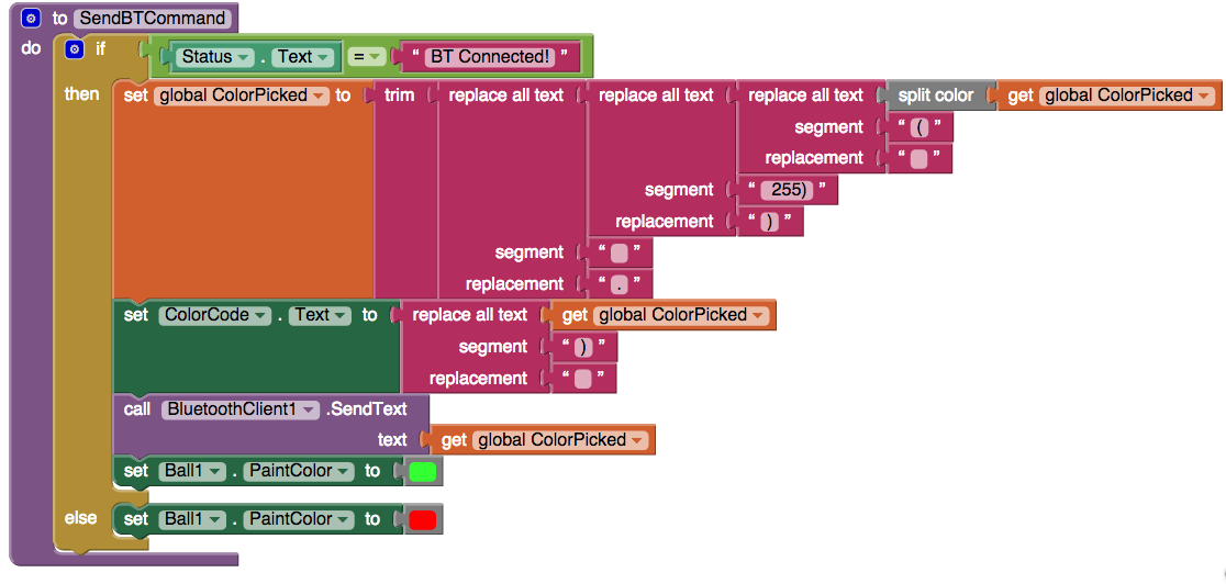
6) Here is the code for RGB color code split and then send to Arduino to change RGB LED color through Bluetooth.
How RGB Color Code was Processed:==*==*==*====*====*====*====*====*====*====*====*====*====*====*==
In App Inventor, the color code string after [Split Color] will be something like “(255 255 255 255)“. What I need in Arduino is only R, G B, so I have to remove last 255.
*** The last 255 is a string in color code and it will be 255 all the time***
For easier string processing, I replace ” “(space) with a “.” (dot).
Then, I send each color code string to Arduino as “255.255.255)“
In side Arduino, I could split R, G, and B easily with the “.”(dot) and use ending “)”(parenthesis) to check if the color code is complete or not.
==*==*==*====*====*====*====*====*====*====*====*====*====*====*==
After you put all these codes into MIT App Inventor 2, you should able to build the code on your PC/Mac to generate an Android .APK to place on your Android phone to test it out with Arduino.
Please do not ask me to post the original code here for you to download. If I do so, no one would download my App from Android Play Store! 😉
If you don’t want to create this App yourself, please Download this App here!
Happy coding!!
Stonez
——————————————————————————————————————–
Part II – Android HC-05 藍芽連線控制彩色 RGB LED
請先看一下底下影片的示範:
MIT App Inventor 的程式代碼如下:
3) 這組程式碼是用來開關 RGB LED
4) 這組程式碼是用來回應點選的顏色並改變 LED 顏色
5) 這組程式碼是用來控制滑過螢幕並即時改變其顏色
6) 這組程式碼是用來把顏色編碼成 RGB 代號並且把這組編碼顏色代號以藍芽送到Arduino該LED依照代碼變色。
Stonez




Hi LUIS,
Are all the images showed up properly for you?
Stonez
Benjamin Vallet & Luis Carlos, it looks like there are some codes missing… let me check it out and get back to you!
Benjamin Vallet & Luis Carlos, it looks like there are some codes missing… let me check it out and get back to you!
Sorry for the delay, please set these variables as below:
initialize global: ColorPicked to “7”
initialize global PreviousColor to “p”
Sorry for the delay, please set these variables as below:
initialize global: ColorPicked to “7”
initialize global PreviousColor to “p”
Well, in App Inventor, the color code string after [Split Color] will be something like "(255 255 255 255)". What I need in Arduino is only R, G B, so I have to remove last 255.
*** The last 255 is a string in color code and it will be 255 all the time***
For easier string processing, I replace " "(space) with a "." (dot).
Then, I send each color code string to Arduino as "255.255.255)"
In side Arduino coding, I split R, G, and B easily with the "."(dot) and use ending ")"(parenthesis) to check if the color code is complete or not.
I hope this helps!
I am not sure about this, but if Serial.parseInt() only read separate data by commas, then you should just replace "."(dot) with a "," (comma).
Look at AI2 blocks step (6), about in the middle part, there's command blocks
***My code was***
Replace all text
Segment " " (space)
Replacement "." (dot)
***Your code should be***
Replace all text
Segment " " (space)
Replacement "," (comma)
Then, it should work!
First, count how long is the string you are spliting. You r example string "255 255 255" does not have any space between "255". I really do not understand why it becomes "2.5.5".
Save your code and send it to me and let me take a look.
Stonez
Glad that works for your!!
Hi Luis, leave your email here. I will try to reply your questions.
Stonez
Hi Andries,
Glad that worked for you!
I know…I am current studying ESP8266 module. See if I could make it work!
No. You will have to make the .aia file yourself. This is part of learning… As for the circle image, I just found it using Google Search with Keywords "circle hue image"
Sorry, you will have to make the .aia file yourself…
Arduino code is in Tutorial Part I.
In App Inventor2:
initialize global: ColorPicked to “7”
initialize global PreviousColor to “p”
Hi KJ,
I think you can, but the whole strip of LED would be the same color only.
W2812S has so many LED and you got to have FASTLED library inside Arduino compiled. Also, on the AppInventor APP, different command has to be created to give WS2812S LED strip different styles of colors and lighting effects.
See the lighting effects below.
http://stonez56.blogspot.tw/2015/06/test-arduino-and-w2812b-led-strip.html
Dan, this is really weird…Please ensure you use exactly the code without modification, no extra space and common or dot.
RGB = "0.0.0)" ; //Send OFF string to turn light off
In the Arduino code, "0.0.0)"; is the instruction to turn light off.
Please make sure you are sending exactly the code from AppInventor.
It's in the Tutorial part I. Grab it here:
http://stonez56.blogspot.tw/2014/09/arduino-android-led.html
調色盤是在Google上找來的
I believe your issue can be fixed by reading tutorial part 1.
Here is the quote:
"
Common Anode connect to 5V.
Note: if you bought common anode LED, then this pin must connect to VCC 5V. If you bought common cathode LED, then this pin must connect to GND"
Let me know if your issues is solved or not.
CurrentX and CurrentY are automatically received in the Dragged event blocks.
X and Y are received in the TouchDown event blocks.
Not sure exact what you would like to do, but in this App, just get RGB color respectively and call the Send BT Command block.
Hi All,
I've added the missing global variables back to the blog.
Check them out! 🙂
I've added the missing global variables back to the blog.
Check them out!
I've added the missing global variable back to this post.
Check them out.
I wish I can come up and iOS version for this, but I don't know how to program this for iOS.
Look at the place where AI2 process the string. Longest string should have 4 numbers with and ending ")". The string in your code definitely too long, "200,244,60,100,25,236…".
No, "SendBTCommand" is a procedure I made myself.
You need to add "BluetoothClient" from the left menu into the App.
After doing this, you will find "BluetoothClien1" to send text.
Look at the "SendBTCommand" for details of how to implement it.
1. 如果你只是按到空白的地方,它的數值就會是 (255 255 255 255).
2. Status 只是顯示 BT 有沒有連線成功而已,沒有其它用途。
1. 先加入一張 Canvas, 再加入一個 color wheel imageSprit 放到Canvas上。
2. 應是程式有誤
3. 只是先給一個定義值,細節我要回去看code
Hi Saytinh,
For WS2811, I have a tutorial with demo code in that page.
http://stonez56.blogspot.tw/2015/06/test-arduino-and-w2812b-led-strip.html
Basically, I use FASTLED library to light up the LED stripe.
Sorry, I'm too busy to do this. You should be able to add a button to that APP to do that job.
如果無法完成,請到 Google Playstore 下載我的 App 使用。
Sorry, as I said in the beginning, please download my free APP from Google Play Store.
Sorry, as I said in the beginning, please download my free APP from Google Play Store.
I'm glad that it worked out for you! 🙂
Hi Nate, quite few people have ran into this issue. Let me post the older version .apk on this blog over the weekend, so whomever need this can give the older version a try.
Stonez
Sorry, it's hard to help with the few descriptions you provided.
Do you mean my App won't light up LED at all?
What's APC file? All Arduino code were provided on this Tutorial.
Sorry, it's hard to help with the information you provided here.
Sorry, I haven't try this APP with LED strip yet, but I think it won't be too hard. Let me find a time to test this out.
X, Y = the position you currently touch.
R,G,B=Shows you the R.G.B color composition to mixed to color you see.
Sorry, I can't understand your question.
"SendBTCommand" (Send BlueTooth Command) is a procedure I made myself in AppInventer.
You need to add "BluetoothClient" from the left menu into the App.
After doing this, you will find "BluetoothClien1" to send text.
Look at the "SendBTCommand" for details of how to implement it.
Hi,
I think the proper solution for you might be W2812S LED strips.
See the lighting effects below.
http://stonez56.blogspot.tw/2015/06/test-arduino-and-w2812b-led-strip.html
SendBTCommand is used to send Bluetooth commands to Arduino from your smartphone. It's a procedure, so you need to create a procedure from AI2 first.
see this document to know how to do it:
http://ai2.appinventor.mit.edu/reference/blocks/procedures.html